Jason's website | home
fuelling circuit for M1's
01Feb2001 Note: This is stuff about my former 1.6 Miata..
06 Jan 2000
Here are the results of an experimental circuit I built to address my lean spot. Am running a Greddy turbo at 6 psi intercooled with the stock fuel pump and the Greddy AFPR. I built this circuit after reading [email protected]/hipsifuel.htm"Dick Bipes 8psi resistor-in-thermosensor-line switch page.
Dyno results are taken with a "Home Dyno" like software I wrote. Results do not include the +9% correction for humidity and temperature.
I tested my AFPR's fuel pressure curve with the engine off and the fuel pump running. The AFPR was pressurized with a plastic squeeze bottle. My fuel pump maxes out at 72 psi with the engine off, and something like 78 psi with the engine running (more voltage available).
The way my first Greddy AFPR was installed, the fuel pressure would go from the factory setting of 41 psi to `72 psi at only 1 psi of boost. It was acting almost like a switch. It should be 41 psi at no boost and +6 to +7 psi of fuel for every 1 psi of boost.
So it would be too rich between 0 and 5 psi, and correct at 5 psi.
On Ray Ayala's suggestion I tried reversing it, and I got the following result:
boost
|
measured fuel pressure
|
correct fuel pressure
|
0
|
41
|
41
|
1
|
41
|
47
|
1.5
|
41
|
50
|
2
|
45
|
53
|
3
|
58
|
59
|
4
|
72
|
65
|
5
|
72
|
71
|
This shows it would be lean from ~0.5psi to 3 psi, and slightly too rich at 5 psi.
On the road, with the Greddy AFPR "normal" (full pressure by 1.5psi), the O2 sensor showed too rich until 5 psi of boost, correct at 6 psi, except for 3700 rpm to 5000 rpm where it was very lean (0.08V).
At first I thought I didn't have enough fuel pump pressure, but 6 psi of boost above 5000 rpm wasn't too lean. If I didn't have enough fuel pressure I would always be lean at 6psi no matter what RPM. So it must be the "volumetric efficiency peak". It happens to me around 4k rpm because my Euro/Asian Miata has the cams of the US auto-tranny 1.6's which have peak torque at 4k rpm (peak volumetric efficiency happens at peak torque) Incidentally my fellow Miataphile Keith with an "Tony'ed" 8psi Sebring leans out at ~4k rpm as well, even though his boost is also flat, his from 3300 to 6000 rpm.
When I reversed the Greddy AFPR, I expectedly got another lean spot, from 0.5 to 3 psi, as well as the one around 4k rpm during full boost.
I have to get that rebuild kit for my BEGI AFPR...
In the meantime I thought of building a circuit that cheats the coolant temperature sensor when my engine leans out. It would still be useful even after I fix my fuel pressure because that 4k lean spot will always be there.
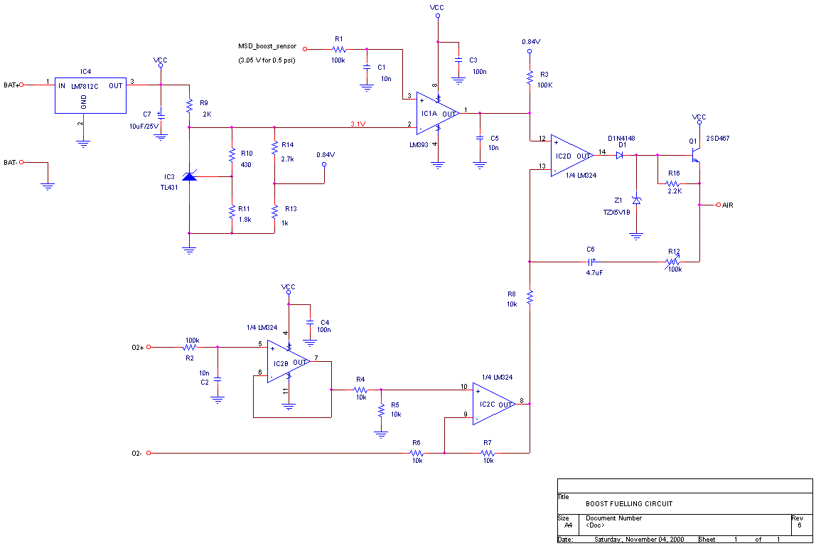
The circuit I built and tested kicks in at 0.5psi of boost, and watches the 02 sensor voltage. If it goes below 0.84V, it will drive the coolant thermosensor voltage wire on the ECU up to maintain 0.84V on the ECU. This way it automatically corrects any lean spots whenever it happens under boost. Since the ECU can only enrichen the mix if it thinks the engine is cold, and cannot lean-out a rich condition, I decided to use the "reversed" Greddy AFPR connection, since it has lean spots and no rich spots. The circuit operates in true closed-loop fashion.
The ECU internally has a ~2.5 kOhm pullup resistor to 5V so one doesn't have to insert a resistor into the coolant thermosensor line to fool the ECU. Just driving its voltage higher will do the trick. The stock ECU sees ~2V at 25oC (81oF) and 0.5V with the engine warm.
And, it's easier to design a circuit to do the latter than a variable resistor effect.
It took me 3 iterations to tune the circuit's feedback loop so the circuit wouldn't oscillate. Now it doesn't oscillate but still overshoots giving a hesitation, which I hope to eventually tune out.
Here are the dyno results:
Torque:

Curve A is with the "normal" Greddy AFPR
Curve B is the Greddy AFPR reversed.
Curve C is same as B but with the circuit in place
Note scale is expanded.
It works! Nearly +15 ft-lbs at 4.6k! See how torque is as good or better than either of the previous runs without the circuit. It seems with the "normal" Greddy AFPR connection, it's too rich at 3.5 to 4k and with the AFPR reversed with the circuit it's correct.
(Note: Dyno figures here don't include ~ +9% SAE correction for high humidity and ambient temperatures. And, port matching and "porting" the exhaust manifold added another 5 ft-lbs and 5 hp)
Subjectively the lean spot with the reversed Greddy from 1-3 psi (2.5k to 3k rpm) is very pronounced because torque rises very rapidly from 3k to 3.7k rpm.
With the fuelling circuit the lean spots are gone and the engine is much stronger around 4k rpm. The torque delivery is smooth is you start at a lower rpm. When the circuit kicks in I feel a brief hesitation as the circuit corrects the air-fuel mix.
The O2 sensor shows a dip in O2 voltage to 0.5V then shoots to 0.9V and then settles to 0.84V. The coolant signal overshoots to 3V during the lean spots and settles at around 2V. Towards redline I can see it still richens the mix but the amount of enrichment goes down. Before the circuit my O2 sensor was showing 0.81V at the top-end, now the circuit maintains 0.84V.
And here are the power curves:

That's +10hp at 4.6k rpm! This is worth more than the 2-3 hp loss at the top end.
That 2-3hp at the very top end - it seems it's true that a bit leaner is stronger at the top. Without the circuit the O2 sensor was reading about 0.81V, with, it's 0.84V.
Here's the schematic of my prototype. It can be improved upon.

I chose the TLC2274 (TI) because it has very high impedance inputs (for the O2 sensor) and because it works on a single supply, and because I had it in my drawer. J The LM7812 is not intended to regulate the voltage but to limit it to 12V max because the '2274 is rated at 16V max. U1 is the 0.5 psi trigger, U2A is a buffer for the O2 sensor, U2B is the error amp. The feedback of the error amp is taken from the coolant signal to improve large signal response (long explanation). The 2N2222 can be any generic TO92 NPN BJT. The Boost sensor signal is taken from the MSD ignition retarder as outlined in Dick Bipes' page.
Another circuit I thought of, if one only suffers from a lean spot at the peak volumetric efficiency point, (I think this is common for AFPR setups), is to not look at the O2 sensor and just drive the coolant sensor voltage up when RPM is at peak volumetric efficiency. This would be open loop rather than closed, so it has the advantage of never overshooting nor oscillating, and correct fuelling if it's tuned right. I sketched a schematic where the circuit would kick in at say 4 psi, then boost the voltage up at starting at 3.5k rpm, rising up in a straight line, peak somewhere, then come back down at 5k rpm. The boost threshold, rpm on and rpm off, as well as maximum coolant voltage boost, can all be adjustable.
15Feb00
And here is my air fuel ratio monitor:

The lowest LED lights up for stoich (0.1v to 0.78v). The 2nd for slightly rich (0.78v to 0.82v). The 3rd is for perfect rich (0.82v to 0.88v), and the top one for too rich (> 0.88v). No LEDs light for lean.
You can redesign it to add LEDs. Perhaps split the stoich region into 2 LED's, and add a lean LED from .02V to 0.1V. The reason I used only 4 LED's is because I'm lazy and I wanted to keep the parts count low to minimize construction effort.
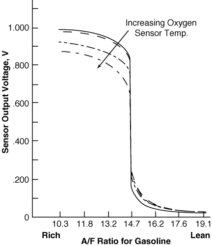
The rational for the voltages is below.
Here is the O2 sensor curve:

email me: [email protected]